¶ QCIOT - Wireless Power Management System
This information should help you get started with the evaluation process. The following are covered in this section:
- Introduction to the QCIOT - Wireless Power Management System.
- Ul sequence of the steps to be followed
- Configurable parameters and their definitions
- Outputs that can be monitored.
¶ INTRODUCTION :
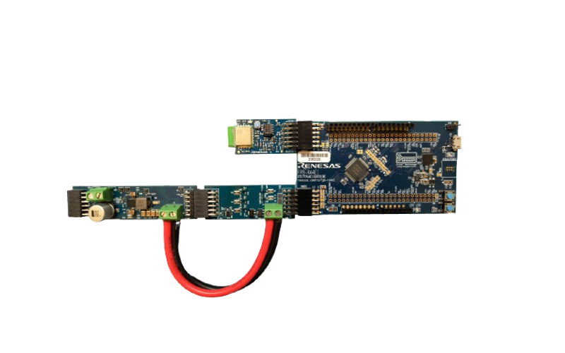
The QCIOT-ELOADPOCZ and QCIOT-006 Power boards are integral components of the Quick-Connect ecosystem, designed for streamlined prototyping and stress testing. The QCIOT-ELOADPOCZ features the SLG4BE46142V programmable mixed-signal IC for I2C-enabled current load selection, while the QCIOT-006 incorporates the RAA211651 60V 5A low quiescent current integrated switching regulator alongside the ISL28023 Precision digital power monitor for output control. Both boards offer standard Pmod Type 6A connections for onboard sensors, facilitating seamless integration with MCU evaluation kits. Notably, they boast Pmod connectors on both sides, enabling daisy-chained connections with additional Type 6/6A boards. Software support within the Renesas IDE (e2 studio) further simplifies device-MCU connectivity, significantly reducing development time.
¶ KEY FEATURES :
- Input voltage range: 4.5 V–60 V.
- Variable load current, up to 5 A.
- Adjustable output voltage (0.8 V to 3.3 V).
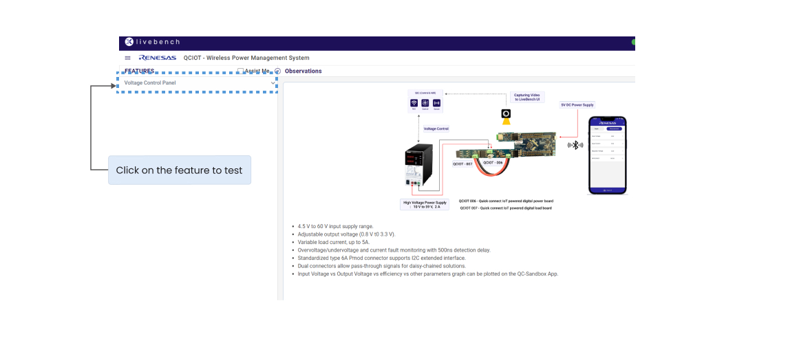
¶ LAB SETUP :
.png)
¶ PROCESS :
1. Press the 'PLUGIN' button to connect to the LiveBench setup.
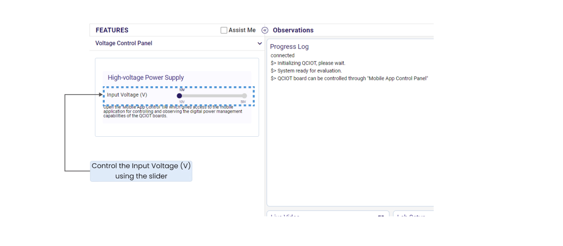
2. Click on Voltage Control Panel and control the Input Voltage(V) which ranges from 10 V to 59 V.
3. All the features the board is capable of can be evaluated for various set parameters as per user requirements.
¶ APPLICATIONS :
- DC power distribution.
- Industrial and computing PoL(Point of Load).
- Programmable Logic Controllers.
- I2C DAC and ADC with alert applications.
¶ SYSTEM BENEFITS :
- Digital power monitor to measure efficiency and load.
- Wide input range DC converter with adjustable output.
- Alerts for over/under load voltage or current.
¶ START WITH EVALUATION :
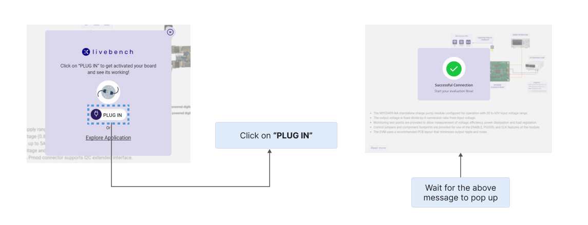
When the user clicks the LoC link, they will land on the cloud-based UI LiveBench for evaluation of QCIOT as shown below. The user will see the overview page, from which the user is allowed to go through the User Guide and Board-related documents to understand the process of Evaluation using LiveBench setup for better understanding and user handholding.
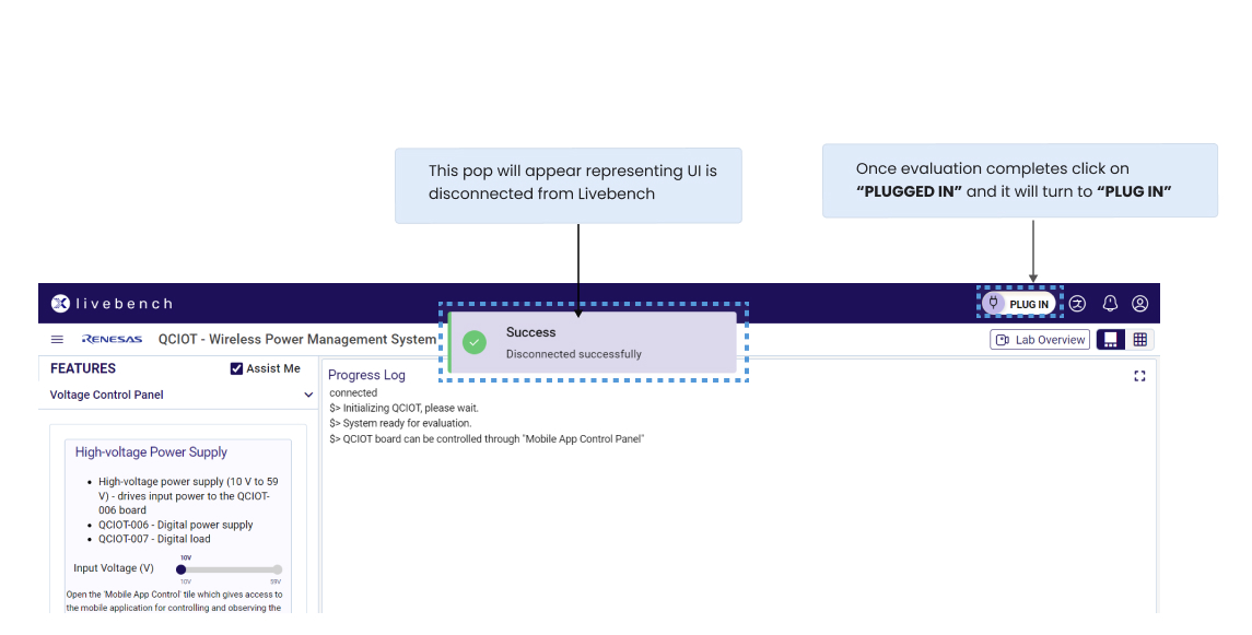
1. Click on the “PLUG IN” (Fig.3.1) to connect with the LiveBench design. Once the connection is established the will be a pop up representing “Successful Connection” (Fig.3.2).
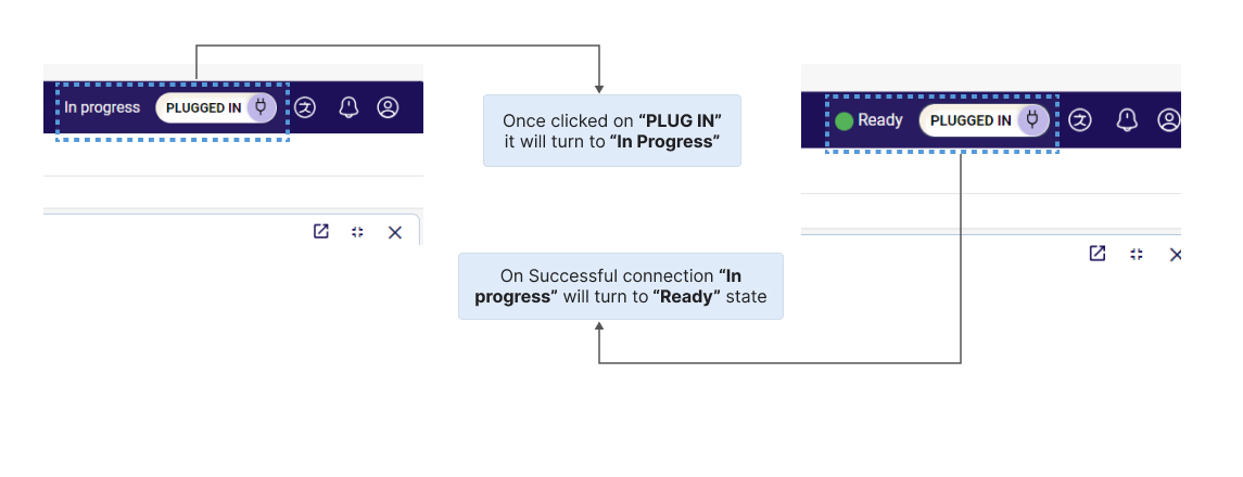
2. After selecting "PLUG IN" , the design will display "In progress" and "PLUG IN" will be changed to "PLUGGED IN" (Fig .4.1), while the system is prepared. After the LiveBench connection is established, the system's status will change from "In progress" to "Ready"(Fig.4.2) , signifying that it is ready for assessment.
3.
.jpg)
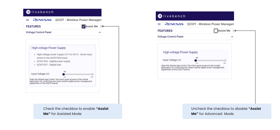
4. Users can choose assisted mode of evaluation to improve their experience by clicking the "Assist Me" (Fig 6.1) checkbox and using the Assisted form of evaluation process flow, or they can simply uncheck the "Assist me" checkbox for advanced mode and use the service when the system is ready for evaluation. A first-time user is advised to use the assisted (Fig. 6.1) based mode, which gives the user comprehensive instructions through messages in the evaluation window.
5.For the selected feature option choose the input/output for the desired configuration parameters.
6.The UI will begin processing the data input, and the "Ready" will change to "In Progress". One by one messages will be updated with the process status in the "Progress log" window.
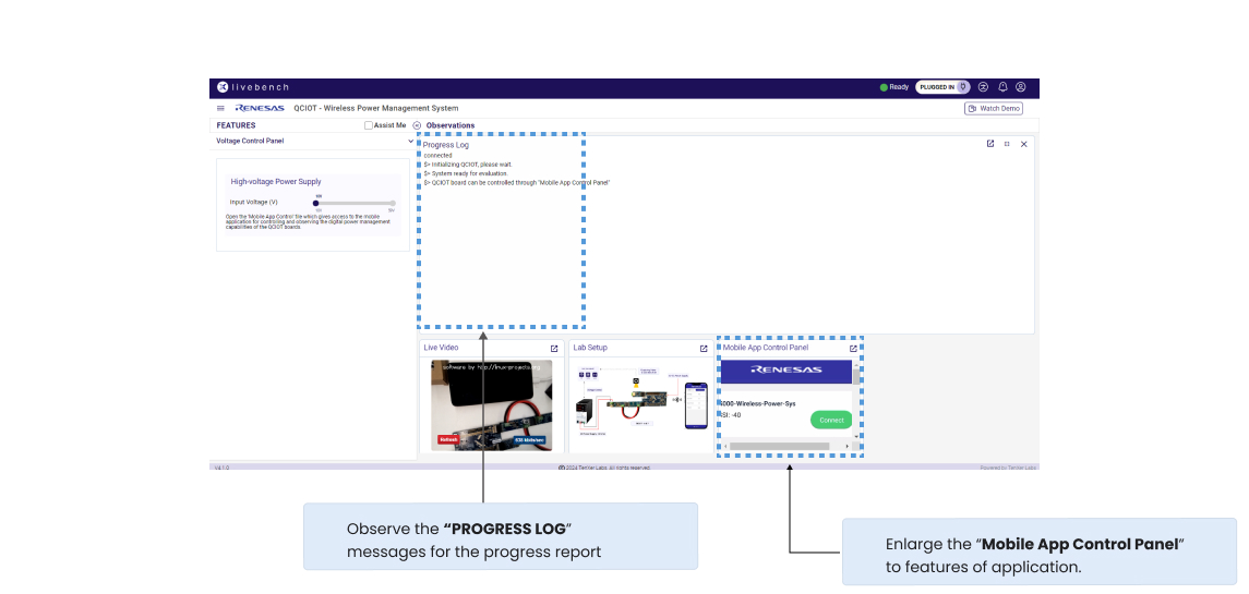
.jpg)
.jpg)
¶ FAQ's:
Q1: What are the key electrical specifications of the QCIOT-5APWRPOCZ?
Ans- 1:
- Input Voltage Range: 4.5 V – 60 V
- Output Voltage Range: 0.8 V – 3.3 V
- Output Current: 0 A – 5 A
- Voltage Monitoring Resolution: 16-bit ΔΣ ADC
- Fault Detection: Overvoltage, undervoltage, and overcurrent monitoring with 500 ns detection delay
Q2: How does the QCIOT-5APWRPOCZ board achieve voltage regulation?
Ans- 2:
The RAA211651 buck regulator uses a Constant On-Time (COT) control scheme to regulate the output voltage. The output voltage is determined by a feedback resistor divider (R10, R11). Additionally, the ISL28023 Digital Power Monitor enables voltage margining via I2C by injecting current through resistor R9 to fine-tune the output voltage.
Q3: What faults can the system detect?
Ans- 3:
The system can detect faults on both the input and output sides, including undervoltage, overvoltage, and overcurrent conditions.
Q4: Can the user set custom fault threshold values?
Ans- 4:
Yes, users can set custom fault threshold values using the QCIOT Sandbox App.
Q5: Can system faults be cleared without restarting the system?
Ans- 5:
Yes, faults can be cleared without restarting the system through the QCIOT Sandbox App.
¶ USEFUL LINKS AND REFERENCES :
- QCIOT-006-QCIOT-5APWRPOCZ (programmable power supply)– Webpage Link
- QCIOT-007- QCIOT-ELOADPOCZ (programmable electronic load) – Webpage Link